Ranging – Feeling the 2 bpm DOCSIS heartbeat

While working with DOCSIS systems it is important to understand the upstream periodic ranging process. Ranging can be seen as the DOCSIS heartbeat between Cable Modem (CM) and Cable Modem Termination System (CMTS). As many people tend to struggle with the details of this process, the goal of this article is to visualize the periodic ranging process. Lets take a closer look at that ranging process – and let’s try to understand where things can go wrong during this DOCSIS heartbeat.
Periodic Ranging, the DOCSIS heartbeat
The upstream periodic ranging process (the initial ranging process is not part of this discussion) can be seen as the DOCSIS heartbeat, meaning it is very critical to the DOCSIS system! When this heartbeat is failing, the real data transmissions (usually using a less robust modulation) will also be subject to packet loss. The modem might even end up losing the upstream channel and/or in worst case reinitializing itself.
More specific, the ranging process is the periodic tuning of the CM transmit parameters, such as timing, frequency and power. The goal is to ensure a perfectly aligned and reliable DOCSIS communication between CM and CMTS. This tuning is maintained per CM and for all of its available upstreams.
The process consists of the CMTS providing a ‘’ranging poll’’ to the CM (unicast ranging opportunity in a DOCSIS MAP message), triggering the CM to send a DOCSIS Ranging Request message (RNG-REQ). Based on the reception of this message, the CMTS provides the CM with the necessary transmit signal adjustments using a Ranging Response message (RNG-RSP). This process, commonly known as “Station Maintenance’’, is repeated periodically to keep the CM within acceptable CMTS reception tolerances. Serious deviation of any of the transmit parameters will cause improper CMTS reception, hence will result in data transmission loss.
Ranging visualized: successful or failing?
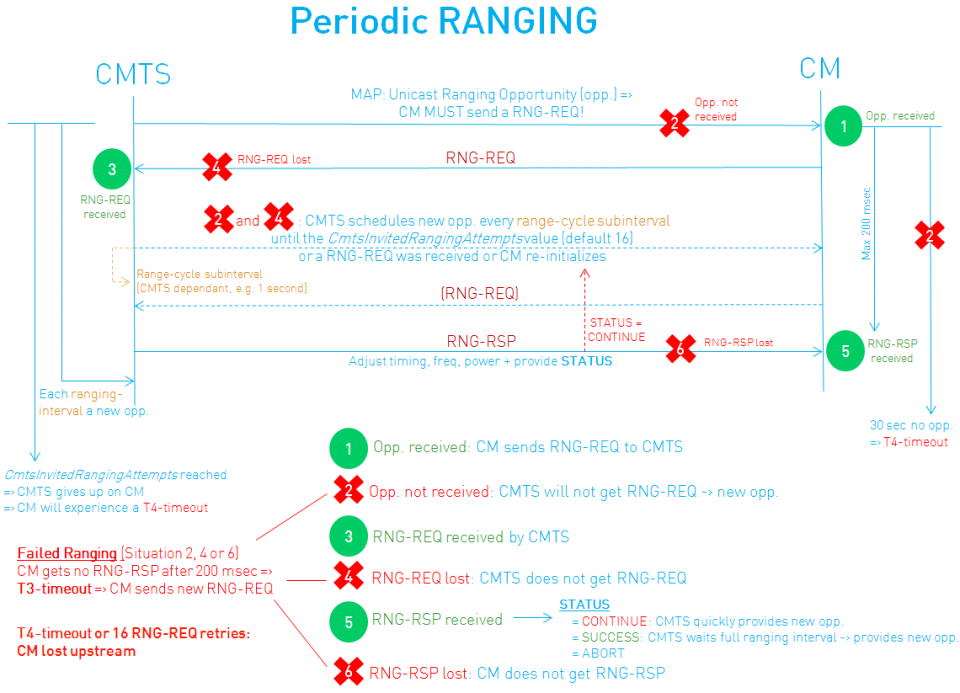
The picture below visualizes this ranging process, it shows how successful ranging takes place (green cases), but also where the communication might fail (red cases) and how the system tries to deal with

2 bpm? Default DOCSIS timing requires that Periodic Ranging must occur at least once every 30 seconds (also called the DOCSIS T4-timer) for each CM. Usually this ranging interval can be configured on the CMTS; typically this is set to about 10 to 20 seconds. When all goes well, it is expected to see the RNG-REQ – RNG-RSP in every ranging interval (”green” cases 1, 3 and 5 on the figure).
However! Due to downstream and/or upstream RF impairments following situations can show up:
- Lost opportunities (MAP) in downstream (case 2)
- RNG-REQ is lost (case 4)
- RNG-RSP is lost (case 6)
- RNG-RSP with Status = Continue (possible within case 5)
Now, how does the DOCSIS system deal with this?
When the CM transmits a RNG-REQ it also starts an internal counter to know when to retransmit in case no answer from the CMTS would arrive. In fact, the CM waits 200 msec (= T3-timeout) to receive a RNG-RSP. In case the CM does not receive that RNG-RSP it flags a T3-timeout and waits for a new ranging opportunity from the CMTS. At the time the CMTS does not receive a RNG-REQ when it expects one, it will schedule a new ranging opportunity according to a ranging “subinterval” (CMTS specific interval). The goal is that the CM can return to a ranging status of SUCCESS as quickly as possible. Every time a RNG-RSP is not received, another CM T3-timeout will be generated. Once 16 of these T3-timeouts have occured, the CM lost the upstream channel. The same process occurs when the received RNG-REQ transmission is not within CMTS tolerances (RNG-RSP status field = “CONTINUE”), except for the increment of the T3 timer of course.
At the time the CMTS provided 16 (by default) ranging opportunities without receiving any RNG-REQ, it will also stop providing ranging opportunities (and such causing a CM T4-timeout).
Losing a channel will result in either “upstream partial service” or result in a reboot of the CM (in case of single channel operation).
Ranging Timeouts – ‘Flapping’
An occurrence of a modem T4 timeout without any modem T3 timeouts often indicates that the MAP message is lost in the downstream, indicating potential downstream issues. For a T3-timeout it can be assumed that if the CMTS did not send the RNG-RSP it most likely did not receive the RNG-REQ due to upstream impairments, therefore T3 timeouts usually indicate upstream impairments.
This means that these modem timeout counters can give useful feedback on the channel quality. Therefore, these counters are often also reflected in so called CMTS flaplist functionalities (for example the CMTS CLI will show ’hits and misses’ and ‘flaps’ for a list of modems). Monitoring this on a multitude of modems can provide better insight into the HFC health and will probably show relation to customer data loss.
Digging deeper
This blog post was intended to show how the DOCSIS ranging really works; and after having read this, it must be clear that ranging is really the 2 bpm heartbeat of your DOCSIS system!
As if this was not detailed enough, in DOCSIS 3.0 quite some extra’s pop in this process, such as CM power reporting, T4-timeout multiplier, partial service, referenced adjustments, Dynamic Range Window, etc. If you are interested in more, consider to read some passages in the DOCSIS specifications or join me in one of our DOCSIS courses; or wait for some future blogpost on the subject!


nice article !!!!
i want to know one thing what is different between
CMTS and DSLAM
CMTS
Hi Bart, thanks for sharing this knowledge and thanks again for the interesting D3.1 course this week! Best regards, Roman
This article has been really helpful to me Bart – Thank you for posting it!
Regards
Rob
Thank you for this article! It was very helpfull for me. I need similar article about docsis 3.2 😉