DOCSIS 3.1 Take Off

The first steps in a new technology are always challenging. To control the take off for the upcoming DOCSIS 3.1 (promising a great deal of capacity potential), it helps to supplement the theory with a more practical view on things. You don’t want to launch a pilot or field trial without some prior practical experience, right? Besides having a nice mind map of DOCSIS 3.1 to help position yourself, wouldn’t it be great to have a visual on the signals itself? And perhaps even recognize certain concepts in that signal? Well, let’s take a signal/spectrum analyzer (R&S® FSW) and find out what the 3.1 OFDM downstream signal really looks like.
Spectrum view
First of all we take a spectrum capture of a DOCSIS OFDM signal. Once the appropriate settings are configured on the analyzer, we get to see the spectrum as shown in the following screenshot.

At first sight we recognize our legacy Single Carrier 6 or 8 MHz downstream QAM channels (at the right side). But we also observe a larger channel; this is the DOCSIS 3.1 OFDM signal having a 96 MHz bandwidth (could range up to 192 MHz). The OFDM channel in fact consists out of thousands of small subcarriers (25 or 50kHz wide). What’s really nice here is that, when we take a closer look, we can also recognize the pilot subcarriers, and even the Phy Link Channel (PLC) can be located! The pilots we see here are the continuous pilots, special subcarriers that exist in the same frequency locations all the time and are used for the modem’s frequency and phase synchronization. These pilots can be easily recognized because they’re transmitted with higher power compared to the data carriers. The PLC is a special narrow channel of 400 kHz wide that carries signaling and boot-strapping information (e.g. OFDM channel parameters and MAC management messages). This PLC can be easily recognized: it lies in the middle of a specially defined 6 MHz wide range containing 8 pilot subcarriers.
Pilot and PLC subcarriers
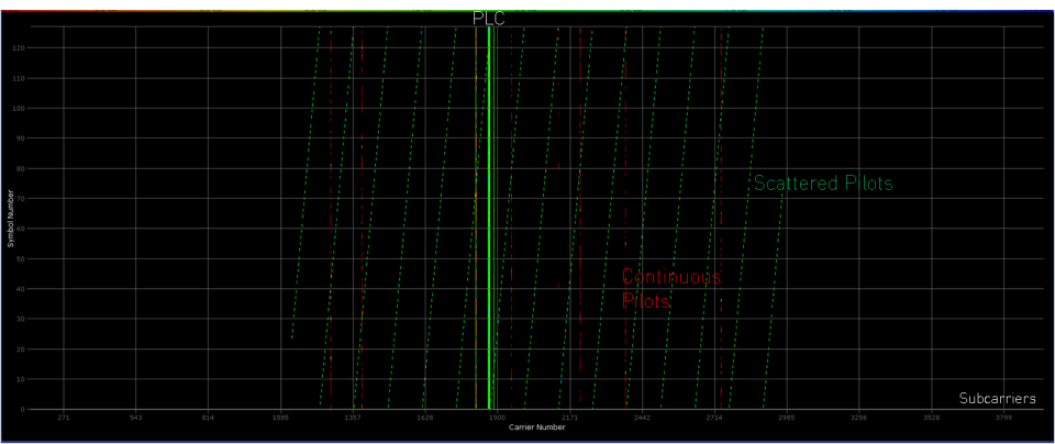
To get into the DOCSIS 3.1 “jet stream” we need to locate and demodulate the PLC. That’s where the pilot subcarriers jump in. In the screenshot below we take a closer look at these.

As we already know, there are 8 PLC surrounding pilots that help to locate the PLC. Furthermore we have the continuous pilots we already spoke of, but this screenshot now also shows the scattered pilots (running in a diagonal way). These pilots have no fixed positions, but rather are scattered throughout the subcarriers so that every subcarrier is eventually used for transmission. This helps the modem to perform channel estimation (determining latency, attenuation and phase shifts).
Constellation displayed
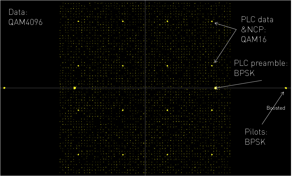
Once way up, we discover the constellations, showing the demodulated signal. The screenshot below for example shows a QAM4096 data modulation, this is the highest mandatory modulation in DOCSIS 3.1. In this case all subcarriers have the QAM4096 modulation. This is not necessary though; there is quite some flexibility in using different modulations for different subcarrier ranges.

Pretty amazing when seeing this for the first time, right? When we take a good look, we can again recognize the pilots as these are BPSK modulated and boosted in power with 6dB. Also the PLC can be located; the PLC preamble is BPSK modulated and the data symbols are 16QAM modulated (for extra protection against errors). In this example also the Next Code Pointers (NCP), used to link codewords to subcarriers within an OFDM symbol, are 16QAM modulated (but this could have been QPSK or QAM64 as well).
Have a nice trip
If you wonder what speeds can be achieved in the provided example, theoretically this could go up to 1 Gbps (RAW rate). How to exactly calculate DOCSIS 3.1 speeds will be explained in a future blog post.
With this practical view on the DOCSIS 3.1 downstream you’re ready for a smooth take off. You still need the theoretical knowledge (get it here), but it’s always good to compare theory with some practice: it often makes it all much easier to understand and for sure easier to remember it!


Can you tell me what piece of equipment is used to view the scattered pilots symbols vs. subcarrier that is shown in the second picture of this article. Thanks!
Hi Marc,
We used a high-end Vector Signal Analyser to get a view on this. Interested in more about DOCSIS 3.1, check https://www.excentis.com/training/docsis-31.